The Nutanix Cloud Bible
The purpose of The Nutanix Cloud Bible is to provide in-depth technical information about the Nutanix platform architecture and how it can enable smooth operations across cloud, edge, and core environments.
» Download this section as PDF (opens in a new tab/window)
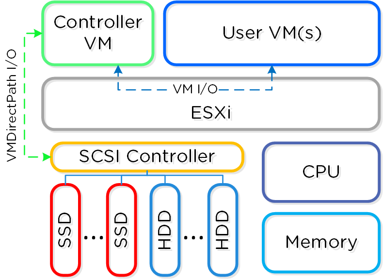
In ESXi deployments, the Controller VM (CVM) runs as a VM and disks are presented using VMDirectPath I/O. This allows the full PCI controller (and attached devices) to be passed through directly to the CVM and bypass the hypervisor.
 ESXi Node Architecture
The following configuration maximums and scalability limits are applicable:
NOTE: As of vSphere 7.0 and AOS 6.8. Refer to AOS Configuration Maximums and ESX Configuration Maximums for other versions.
When doing benchmarking on ESXi hosts, always test with the ESXi host power policy set to 'High performance'. This will disable and P- and C- states and will make sure the test results aren't artificially limited.
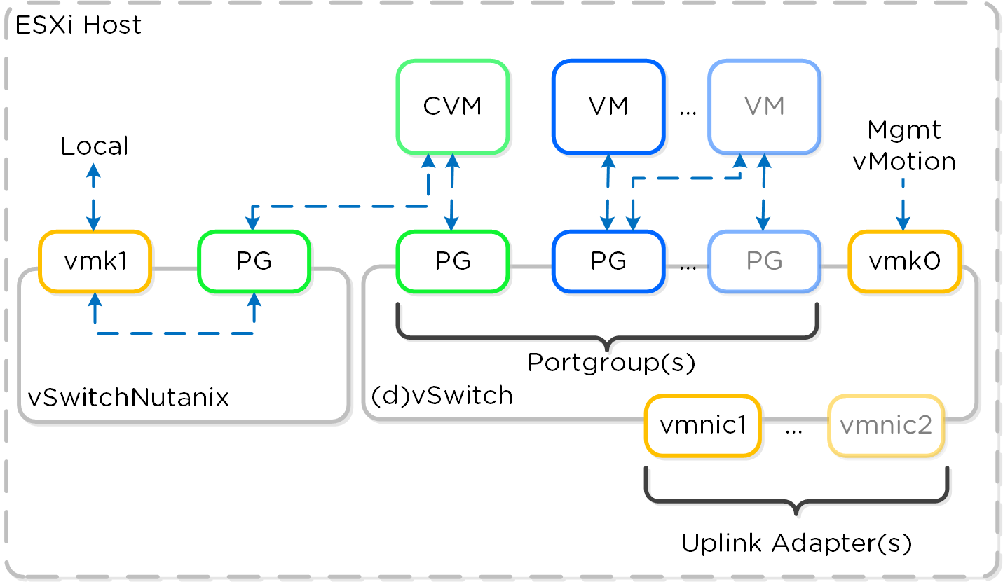
Each ESXi host has a local vSwitch which is used for intra-host communication between the Nutanix CVM and host. For external communication and VMs a standard vSwitch (default) or dvSwitch is leveraged.
The local vSwitch (vSwitchNutanix) is for local communication between the Nutanix CVM and ESXi host. The host has a vmkernel interface on this vSwitch (vmk1 - 192.168.5.1) and the CVM has an interface bound to a port group on this internal switch (svm-iscsi-pg - 192.168.5.2). This is the primary storage communication path.
The external vSwitch can be a standard vSwitch or a dvSwitch. This will host the external interfaces for the ESXi host and CVM as well as the port groups leveraged by VMs on the host. The external vmkernel interface is leveraged for host management, vMotion, etc. The external CVM interface is used for communication to other Nutanix CVMs. As many port groups can be created as required assuming the VLANs are enabled on the trunk.
The following figure shows a conceptual diagram of the vSwitch architecture:
 ESXi vSwitch Network Overview
It is recommended to have dual ToR switches and uplinks across both switches for switch HA. By default the system will have uplink interfaces in active/passive mode. For upstream switch architectures that are capable of having active/active uplink interfaces (e.g. vPC, MLAG, etc.) that can be leveraged for additional network throughput.
©2025 Nutanix, Inc. All rights reserved. Nutanix, the Nutanix logo and all Nutanix product and service names mentioned are registered trademarks or trademarks of Nutanix, Inc. in the United States and other countries. All other brand names mentioned are for identification purposes only and may be the trademarks of their respective holder(s).